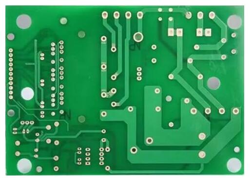
In PCB production process, drilling is very important. The so-called drilling is to drill the required through holes on the copper clad laminate to provide electrical connection and fix devices. If there is a problem in the via process, the device can’t be fixed on the circuit board, which will affect the use or the whole board can’t be used. Therefore, drilling is very important.
What Are The Common Problems in Drilling Process?
1. Broken Drill Bit
Causes:
- Improper drilling nozzle, improper operation, insufficient bit speed or too high feed rate.
- When drilling, the depth of the spindle is too deep, resulting in poor chip removal of the drill nozzle and hanging.
- The grinding times of drill tip are too many, or the service life is too long.
- When fixing the base plate, the adhesive tape is too wide or the aluminum sheet or plate of the cover plate is too small.
Solution:
- Check the change of spindle speed and the stability of spindle. If there is copper wire that affects the uniformity of speed, it should carry out corresponding maintenance or replacement.
- Check whether the air pipe of pressure foot is blocked. Adjust the state between the pressure foot and the drill bit, keep the tip of the drill tip from being exposed and check the pressure data when the pressure foot is compressed.
- Check the geometry and wear of the drill tip and select the drill tip with appropriate length of chip withdrawal groove. Select the appropriate amount of feed, reduce the feed rate to the appropriate number of layers.
- Select the cover and base plate with appropriate surface hardness and flatness. Check the fixed state and width of the adhesive tape. Replace the aluminum sheet of the cover plate and check the size of the plate.
2. Hole Loss
Causes:
- There is no aluminum sheet or reverse plate when drilling.
- The effective length of the drill tip can’t meet the needs of the thickness of the drill stack.
- The plate is special, which is caused by the front of the batch.
Solution:
- Aluminum sheet and negative plate are used in production to protect the hole ring.
- Grab the drill nozzle, check the position of the drill nozzle is correct. And then start the machine. Generally, the drill nozzle should not exceed the presser foot.
- Visually check the effective length of the drill nozzle before the drill nozzle is put on the machine. Measure and check the stack number of the available production plates.
- When setting parameters for drilling special plate, the parameters should be selected according to the quality. The feed speed should not be too fast.
3. Plug Hole
Causes:
- The effective length of the bit is not enough.
- Substrate material problem.
- The backing plate is reused.
- The feed speed of the drill tip is too fast, and it is not matched properly with the rising speed.
Solution:
- Select the right length of drill bit according to the stack thickness, which can be compared with the stack thickness of production plate.
- Set the drilling depth reasonably and select the substrate material with good quality.
- Select the best processing conditions and adjust the dust suction of drilling hole properly.
4. Missed Drilling
Causes:
- Program error.
- The program is deleted artificially or unintentionally.
- The data of drilling rig is not read.
Solution:
- Separate the broken drill board and check it one by one.
- In case of errors in engineering procedures, the project shall be changed immediately.
- During the operation, do not change or delete the program at will.
5. Criticism Front
Causes:
- The drill bit is worn and the blade is not sharp.
- There are sundries between the base plate and the base plate, and between the base plate and the base plate.
- The substrate is bent to form voids.
Solution:
- When nailing the board, clean up the sundries between the base plates, especially the multi-layer board.
- The base plate deformation should be pressed to reduce the gap between the plates.
- Add aluminum sheet to cover plate for protection during the drilling.
- When drilling special plate, the parameters should not be set too fast.
6. Rough Hole Wall
Causes:
- Improper selection of cover material.
- The vacuum degree of the fixed bit is insufficient.
- The cutting edge of the top angle of the drill bit is broken or damaged.
- The spindle deflection is too large.
Solution:
- Adjust the feed rate and speed to achieve the best match.
- Check the vacuum system and spindle speed of CNC drilling rig change.
- Adjust the tool return rate and bit speed to achieve the best state.
- Improve the chip removal performance and check the status of chip removal groove and cutting edge.
7. There is a White Circle on The Edge of The Hole
Causes:
- Thermal stress and mechanical force are produced during drilling, which results in local fragmentation of the substrate.
- The size of glass cloth knitting yarn is coarse.
- Poor quality of substrate material.
- The drill bit is loose and not fixed tightly.
Solution:
- Check the wear condition of drill nozzle, and then replace or regrind it.
- Choose the glass cloth woven by fine glass yarn.
- Check whether the set feed is correct.
- Check whether the diameter of drill nozzle handle and the clamping force of spindle spring clamp are enough.
8. The Hole is Not Drilled Through The Base Plate
Causes:
- Improper depth, uneven thickness of base plate and insufficient length of drilling nozzle.
- Half of the cutter or drill bit is broken, and the hole is not penetrated.
- The front of the batch is penetrated into the hole to form impervious copper.
- The spindle clamping nozzle is loose, and the drilling nozzle is pressed short in the process of drilling.
Solution:
- Check the platen is flat and the depth is suitable. Measure whether the length of the drill tip is enough and adjust it appropriately.
2. Check and eliminate the source of the batch front, and polish the batch front. - Adjust the spindle looseness, clean or replace the cable nozzle.
- Check whether the bottom plate is added before the double-sided board is mounted.

