Fault Characteristics and Maintenance of PCB Capacitor Damage
The fault caused by capacitor damage is the highest in electronic equipment, especially the damage of electrolytic capacitor is the most common.

The damage of capacitance is shown as follows: the capacity becomes smaller, total loss of capacity, electric leakage and short circuit.
Capacitors play different roles in the circuit, and the faults caused by them have their own characteristics.
In the industrial control PCB, digital circuit accounts for the vast majority. The capacitor is mostly used as power filter and less used as signal coupling and oscillation circuit. If the electrolytic capacitor used in the switching power supply is damaged, the switching power supply may not vibrate and have no voltage output. Or the output voltage filtering is not good, and the logic of the circuit is confused due to the unstable voltage, which shows that the machine works well or fails to start. If the capacitor is between the positive and negative poles of the power supply of the digital circuit, the fault performance is the same as above.
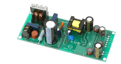
This is particularly obvious on the computer motherboard. After several years of use, many computers sometimes fail to turn on the computer, and sometimes they can turn on the computer. When you open the chassis, you can often see the phenomenon of electrolytic capacitor bulging. If you remove the capacitor and measure the capacity, it is found that it is much lower than the actual value.
The life of the capacitor is directly related to the ambient temperature. The higher the ambient temperature is, the shorter the life of the capacitor is. This law is applicable not only to electrolytic capacitors, but also to other capacitors. Therefore, when looking for faulty capacitors, it is important to check the capacitors close to the heat source, such as the capacitors near the heat sink and high-power components. The closer they are, the greater the possibility of damage.
Some capacitors have serious leakage, even hot hands when touching with fingers, so this kind of capacitor must be replaced.
In the maintenance of good and bad faults, excluding the possibility of poor contact, most of them are caused by capacitor damage. Therefore, when encountering this kind of fault, you can focus on checking the capacitor. It is often surprising to replace the capacitor.
Characteristics and Discrimination of Resistance Damage
Resistance is the most numerous component in electrical equipment, but it is not the component with the highest damage rate. Open circuit is the most common resistance damage, larger resistance is rare, smaller resistance is rare. The common ones are carbon film resistance, metal film resistance, wire wound resistance and safety resistance.
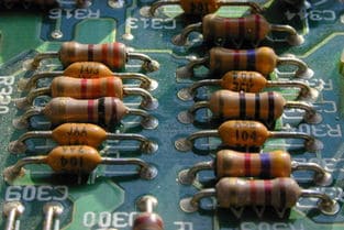
Carbon film resistors and metal film resistors are the most widely used. One of the characteristics of their damage is the low resistance (100 Ω Below) and high resistance (100k) Ω The middle resistance (such as hundreds to tens of thousands of Ohm) is rarely damaged. The low resistance is often burnt and blackened when it is damaged, which is easy to find, while the high resistance has little trace when it is damaged.
Wire wound resistance is generally used for large current limiting and the resistance value is not large. When the cylindrical wound resistance is burnt out, some will be blackened or the surface will be cracked, some will not have any trace. Cement resistance is a kind of wire wound resistance, which may break when burned out, otherwise there is no visible trace. When the safety resistor is burnt out, some surfaces will blow off a piece of skin, and some have no traces, but they will never scorch and blacken. According to the above characteristics, when checking the resistance, we can focus on it and quickly find out the damaged resistance.
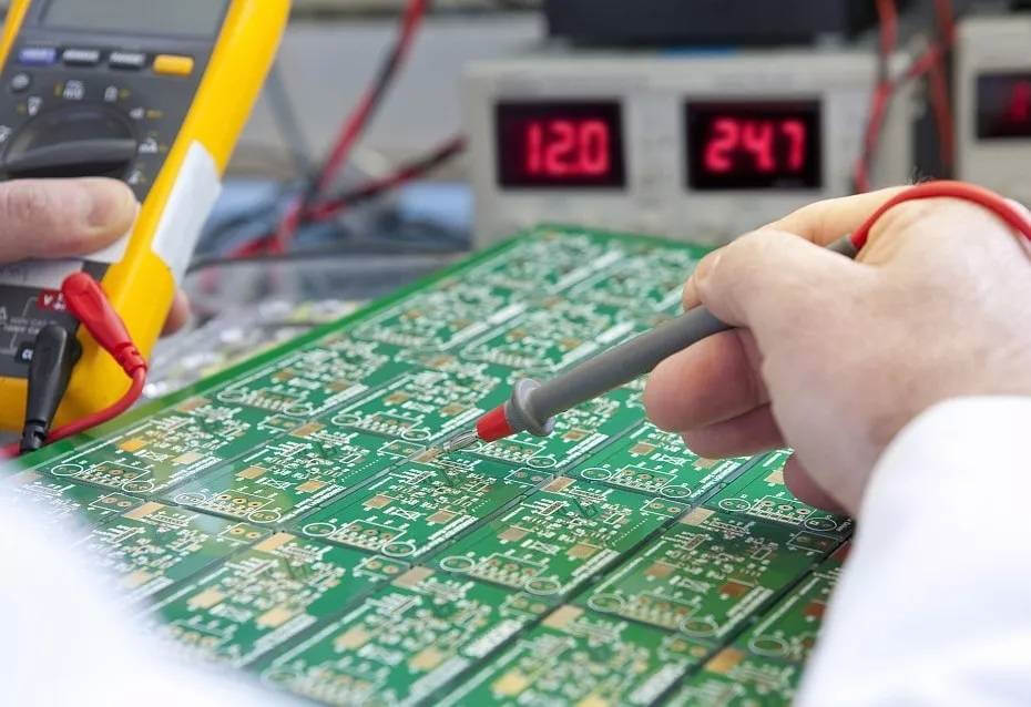
According to the characteristics listed above, we can first observe whether the low resistance on the circuit board is blackened, and then according to the characteristics that most of the resistance is open or the resistance value becomes larger when the resistance is damaged, and the high resistance value is easy to be damaged, we can directly measure the resistance value at both ends of the high resistance value on the circuit board with a multimeter, if the resistance value is larger than the nominal resistance value, If the measured resistance is smaller than the nominal resistance, it is generally ignored. In this way, each resistor is measured on the circuit board.
How to Judge The Quality of Operational Amplifier?
It is difficult for many electronic repairers to judge the quality of operational amplifier. The ideal operational amplifier has the characteristics of “virtual short” and “virtual break”, which are very useful for the analysis of linear operational amplifier circuits.
In order to ensure linear operation, Op Amp must work in closed loop (negative feedback). If there is no negative feedback, the open-loop amplifier becomes a comparator. If you want to judge whether the device is good or bad, you should first distinguish whether the device is used as amplifier or comparator in the circuit.
No matter what type of amplifier is, there is a feedback resistor RF, so we can check the feedback resistor from the circuit during maintenance. Use a multimeter to check the resistance between the output end and the reverse input end. If it is too large, such as several M Ω Above, we can probably be sure that the device is used as a comparator. If the resistance is smaller, 0 Ω To tens of K Ω, Then check whether there is a resistance connected between the output end and the reverse input end. If there is one, it must be used as an amplifier.
According to the principle of virtual short of the amplifier, if the operational amplifier works normally, the voltage at the same input and reverse input must be equal, even if there is a difference, it is mv level. Of course, in some high input impedance circuits, the internal resistance of the multimeter will have a little influence on the voltage test, but it will not exceed 0.2V in general. If there is a difference above 0.5V, The amplifier must be broken!
If the device is used as a comparator, the same input and reverse input are allowed to be different,
When the same direction voltage > reverse voltage, the output voltage is close to the maximum positive value.
If the same direction voltage is less than the reverse voltage, the output voltage is close to the maximum value of 0V or negative (depending on dual power supply or single power supply).
If the detected voltage does not comply with this rule, the device will be broken!
In this way, you don’t have to use substitution, you don’t have to remove the chip on the circuit board to judge whether the op amp is good or bad.

