Many engineers still have such problems after debugging PCB. We summarize the steps of debugging. Last article we introduce the first and second steps: detection before power on & power on test. This article we will introduce the other work in the debugging of electronic circuit.
Step 3: Other work in the debugging of electronic circuit
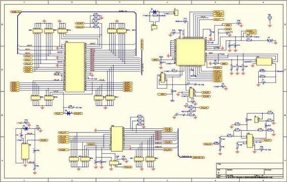
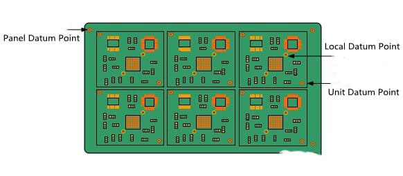
- Develop commissioning steps and measurement methods according to the working principle of the system to be adjusted, determine the test points, mark the positions on the drawings and boards, draw out the record table of commissioning data, etc.
- Set up the commissioning bench, which is equipped with the necessary commissioning instruments. The equipment shall be easy to operate and easy to observe. Students often don’t pay attention to this problem. The work table is very disordered in the process of making or adjusting the machine. Tools, books, clothes and other things are mixed with the instruments, which will affect the debugging. Special tips: during the production and commissioning, the table must be arranged clean and tidy.
- For hardware circuits, the measurement instrument shall be selected according to the system being adjusted, and the accuracy of the measuring instrument shall be better than that of the measured system.
- The commissioning sequence of electronic circuit is generally carried out according to the signal flow direction. The output signal of the circuit that has been debugged before is regarded as the input signal of the next level, creating conditions for the final unified adjustment.
- The digital circuit realized by PLC shall be used to input, debug and download the source file of PLC, and connect the PLC and analog circuit into a system for overall debugging and result test.
- During commissioning, the experiment phenomenon shall be observed and analyzed carefully, and the record shall be made to ensure the integrity and reliability of the experimental data.
Whether the test results are correct or not is greatly affected by the correctness of the test quantity and the test accuracy. In order to ensure the test results, the test error must be reduced and the test accuracy should be improved. For this reason, the following points should be paid attention to:
1. Use the grounding terminal of the test instrument correctly.
In all cases, the electronic instruments of the grounding case shall be used for testing. The grounding terminals together shall be connected with the grounding terminal of the amplifier. Otherwise, the interference introduced by the instrument casing will not only change the working state of the amplifier, but also make the test results error.
According to this principle, when debugging the emitter bias circuit, if VCE needs to be tested, the two ends of the instrument should not be directly connected to the collector and emitter, but VC and ve should be measured respectively to the ground, and then the two are subtracted. If a multimeter powered by a dry battery is used for testing, it is allowed to cross directly between test points because the two input terminals of the meter are floating.
2. The input impedance of the instrument used for measuring voltage must be far greater than the equivalent impedance at the measured place.
If the input impedance of the test instrument is small, it will cause shunt in the measurement, which will bring great error to the test results.
3. The bandwidth of the test instrument must be greater than that of the circuit under test.
4. Select the test point correctly.
When the same instrument is measured, the measurement points are different, and the errors caused by the internal resistance of the instrument will be different.
5. The measurement method should be convenient and feasible.
When the current of a circuit is needed to be measured, the voltage is generally measured as far as possible without current measurement, because the voltage measurement does not need to change the circuit. The test is convenient. If you need to know the current value of a branch, you can get it by measuring the voltage at both ends of the resistance on the branch and converting it.
6. During commissioning, not only careful observation and measurement, but also good record.
The contents of the record include experimental conditions, observed phenomena, measured data, waveform and phase relationship. Only with a large number of reliable experimental records and comparison with theoretical results can we find the problems in circuit design and improve the design scheme.

