Rigid-flex Board Introduction
- The combination of hardware and software has been developed for more than 25 years, but it has always been regarded as a special and expensive board.
- At first, it was used in aerospace and military. In the past few years, it has successfully transferred to the electronic consumer market.
- Because of its flexible connection performance, it is widely used in handsets, DSCs and DVCS.
Definition of Rigid-flex Board
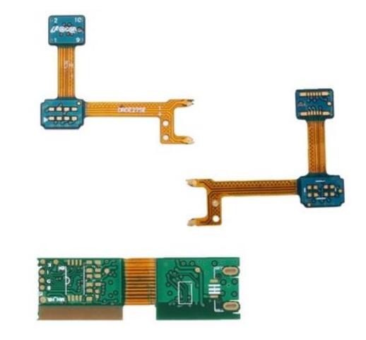
Rigid-flex printed board or F / R PWB, as its name implies, is a printed board mixed with hard board and soft board, which is mainly composed of two or more hard boards and one or more soft boards. The hard board part provides installation and welding of components, and the soft board part provides connection.
Advantages
- Reliable use
- Save space
- Eliminate wiring errors
- 3d interconnection
- Reduce cost (reduce system complexity and simple assembly)
Typical Processing Method of Rigid-flex Boards
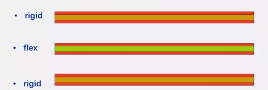
6L Rigid-Flex
- 2L flex (1 pcs of material)
- 4L rigid
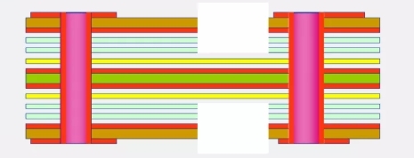
- Print and etch flex
- Print and etch inside faces of rigid layers
- Z axis machine inside face of capping layers
- Machine no-flow prepreg
- Bond coverlay onto flex surface
- Final bond
- Vacuum bond
- No-flow prepreg
- Mechanical drill
- Include ‘vent’ holes in flex windows.
- Plasma desmear
- Print Copper plate
- lmage outer layers
- ‘vent’ holes taped over
- Final rout
- ‘Z’ axis rout windows
- Electrical Test
- Mechanical drill
- lnclude ‘vent’ holes in flex windows.
- Plasma desmear
Processing Concerns of Rigid-flex Boards
Materials
For the flexible part, when subjected to thermal stress, the expansion of z-axis may break the hole copper of soft and hard bonding plate.
Process
1. Press fit. 2. Alignment. 3. Decontamination (plasma treatment method). 4. Electroplating.
Rigid-flex Capability of US Makers
Feature | Standard | Non-Standard |
Flex base material | Polymide (PI) Adhesiveless PI |
|
Adhesive | Acrylic | Epoxy |
Surface Coating | Polyimide Coverlay | Flexible Solder Mask |
Rigid Base Material | FR-4/Polyimide-Glass | FR-5 |
Surface Finish | HASL/Chem.Ni/Au | Selective Ni/ Au |
Number of Layers | <20 | 30 |
Dielectric Thickness | 50ևm | 25ևm |
Lines & Spaces | 150/150ևm | 75 ևm |
Boards Size | Not specific | 550mm x 400mm |
Aspect Ratio | <5 | 7 |
Total Thickness | Not specific | 4 mm |

