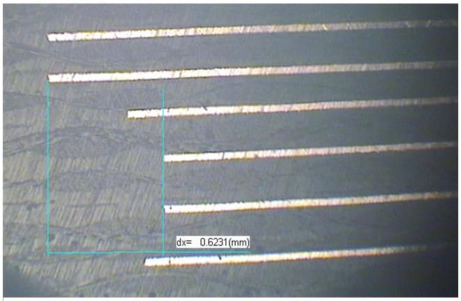
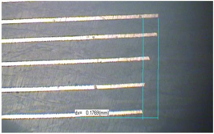
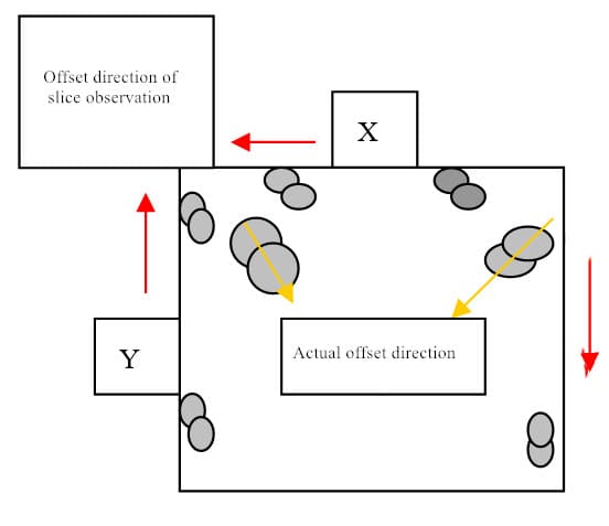
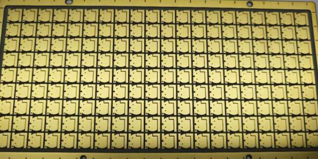
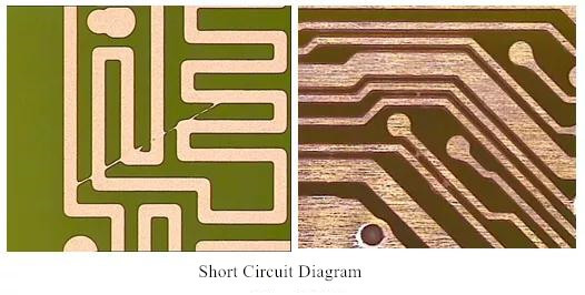
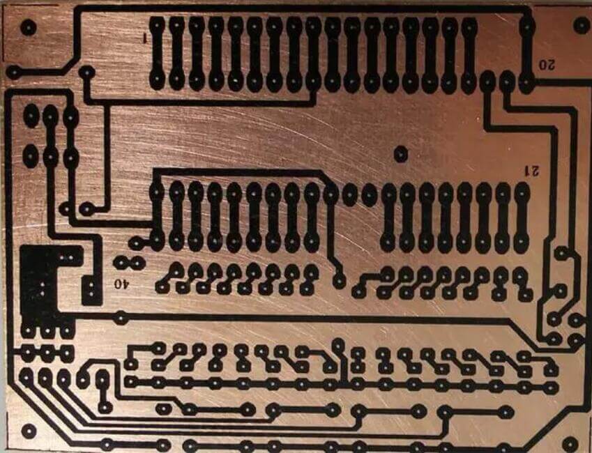
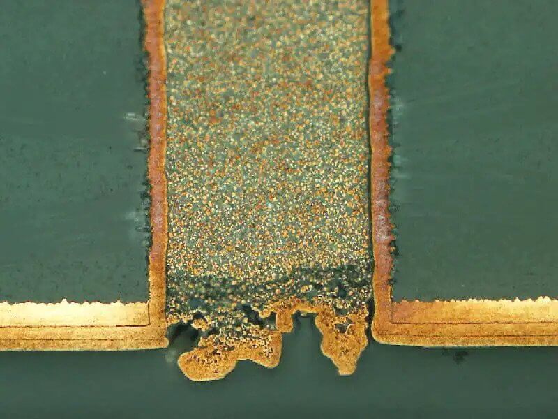
With the gradual development of PCB technology in China, the share of multilayer boards (especially high-level products) in our enterprises is becoming more and more important. While developing and producing these products, we always encounter the problem of short circuit to ground caused by expansion and contraction, alignment deviation and lamination deviation, which has been bothering us all the time. The data that can accurately measure these offsets as the direction of improvement measures has become the focus of our research. I have also seen some technical engineers’ methods of measuring the offset, which are too large and unscientific (see Fig. 1 and Fig. 2), and it is difficult to reflect the original appearance of the facts. After many studies and verification, I have explored a set of more accurate measurement methods, which can not only accurately measure the offset data, but also accurately measure the offset direction and angle, I hope it can bring some help to friends in the industry who are troubled by this.
Problem Phenomenon
At first glance, the offset has 25mil, but what is the actual result? It can be seen from (Figure 2).
The above (Fig. 2) is the right half of the same position. It can be seen that the length of the longest choke point is 33mil longer than the length of the shortest choke point, so it can be imagined how much moisture there is in the previously measured unilateral offset of 25mil. This illusion is caused by the alignment of the choke block in the Y direction, the lamination offset, the offset in the XY45 degree direction, and the inconsistency of the inclined plane of the slice itself and the etching degree of the upper and lower inner core plates. Under this condition, we use the length measurement method to measure the inner layer offset. What is the visible error.
The position of the measuring choke point represents the deviation of the reference point, which can reflect the real offset of the object position. Here, we can define it as the position measurement method.
Explanation of terms
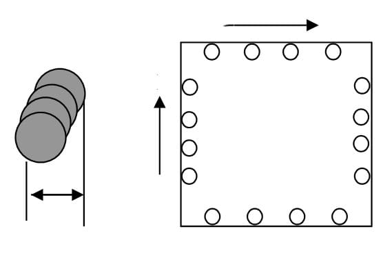
Flow blocking point: a circular point with a certain spacing designed at the edge of the plate to prevent excessive outflow of resin glue during lamination, and each layer is designed at the same position.
Length measurement method: This paper defines the method of unilateral length distance measurement to determine the offset between layers.
Position measurement method: determine the direction offset between the positions of two objects by measuring the accurate representative points of two objects.
Slicing
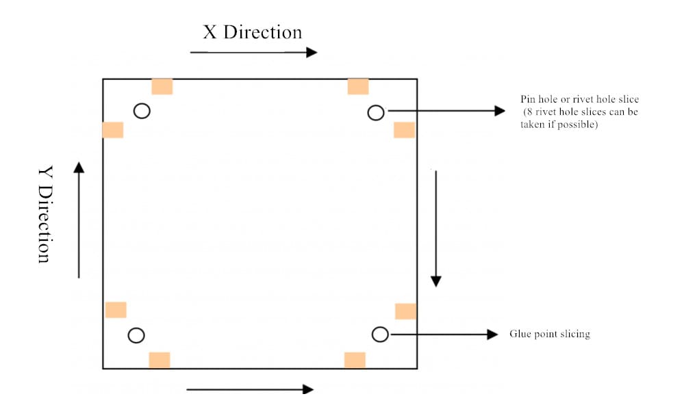
1. Take two slices and four rivet or pin positioning holes at both ends of each side of the laminate respectively, take one slice along four directions (try to take the area with complete choke points), and mark the corresponding position symbols on each slice and board edge. The sampling location is shown in Figure 3.
2. Grind, polish and micro etch the sampled slices according to the corresponding serial number. The slicing of glue flow point shall be grinded in X and Y directions at least. The grinding shall be flat, and the part displayed by the measured figure shall be as small as possible to facilitate measurement.
Offset Measurement
1. Measurement method of alignment offset.
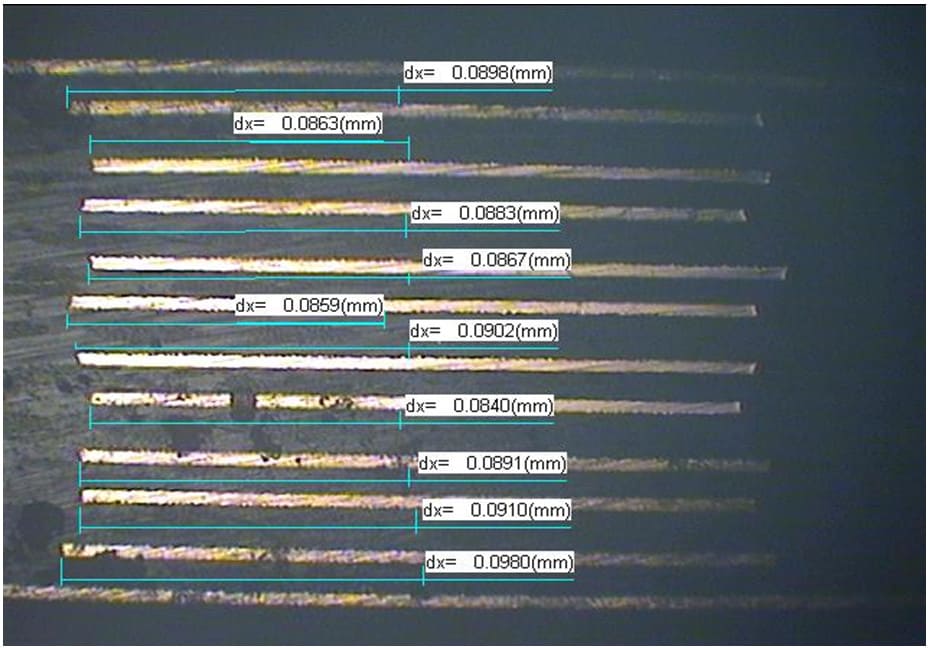
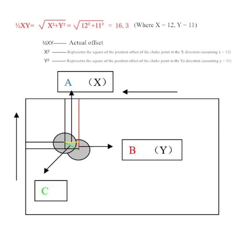
- First measure and record the exposed length of each choke point in the X direction with the 40x mirror of the metallographic microscope, and then measure the length of 1 / 2 of it and mark it as the representative reference point of the center of the circle. As shown in Figure 4, then measure the deviation length of the upper and lower datum points of the same core plate, that is, the offset in the X direction, and mark its offset direction at the edge of the plate (the choke point of one layer can be set as the standard, and the offset of the other layer can be used as the offset direction), and then measure the deviation length of the two datum points in the Y direction of the same core plate of the same slice according to this method, It is the offset in the Y direction, and the offset direction (the same as the X direction) is marked on the plate edge, as shown in Figure 5.
As can be seen from Fig. 5, the offset directions of the x-axis and y-axis choke points are not offset in the same direction. From the perspective of solid geometry, the offsets in the X and Y directions viewed from the slice are actually offsets in the direction of a certain angle with the X and Y axes (as shown in Figure 5).
- Thus, the position of the circle can represent the measurement data of the relationship and its offset, and the data of the actual offset can be calculated by using the Pythagorean theorem formula (see Figure 6).
Of course, this can only calculate the offset at a certain angle with the X and Y axes. Only by calculating its offset angle can it more accurately reflect its offset.
- We can use the calculation formula of trigonometric function basic theory to calculate the actual offset direction of this point.
According to the theory of right angle triangle and the known side length of right angle triangle, 3 can be calculated:
Let B = 11 and C = 16.3
sinA= B/C=11/16.3=0.67
(the scientific calculator can find out that its angle is 42 °)
The position of slice grinding and observation shows that the offset angle of the choke point of the lower layer (based on the upper layer) is in the direction of 42 ° with the measured x edge (i.e. in the direction of 48 ° with the Y edge). See Figure 6 for details.
Thus, even if the offset and offset direction of one point are calculated, the offset and offset direction of the other seven points can be calculated in this way, and the offset of the whole plate can be clearly seen.
2. Measurement method of maximum offset
- Similarly, use a 40x mirror to measure and record the length of each choke point in X and Y directions, and then measure the length at 1 / 2 of it and mark it as the reference point. Then measure the deviation length of the two benchmark points farthest away from the X and Y directions, that is, the maximum offset in the X or Y direction, and mark the offset direction and number of layers on the board edge. Then measure the deviation distance in the Y and X directions of the same slice and the same layer according to this method, that is, the corresponding offset in the Y or X direction, and mark the offset direction and number of layers on the board edge. (as shown in Figure 4 and Figure 7).
- The calculation method of offset and offset angle is the same as the previous calculation method. The only difference is that the maximum offset of X and Y groups should be calculated and compared. The maximum value is the maximum offset of this point, and the maximum offset of the other 7 points can be calculated in turn.
3. Measurement method of lamination offset
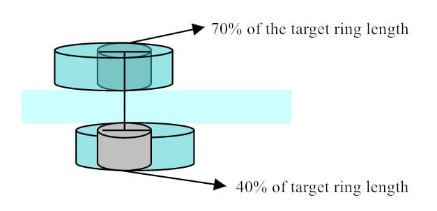
- Observe the slice of the laminated positioning hole with the same cutting direction as that of the two glue flow point slices, measure the central reference position point of the target hole, and calculate the percentage of the reference position in the target ring position. As shown in Figure 8.
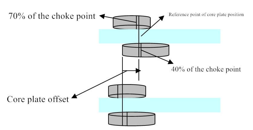
- According to the percentage of the reference point in the target ring, find a choke point slice with the same and similar cutting direction, and determine the location reference point of the core plate choke point according to the same percentage distribution. (if the point found is not on a straight line, the middle position of the two points can be taken as the reference point) as shown in Figure 9.
- Then measure the deviation distance in X and Y directions of the reference points of the upper and lower core plates of this slice, and then mark its offset direction (as shown in Figure 9).
Note: Due to the variation in the production process, it is impossible to completely coincide 70% of the upper choke point and 40% of the lower choke point like the target hole, so only the center position of the two points can be taken as the reference point.
- Use Pythagorean theorem to calculate the real offset in X and Y directions.
- As for the calculation method of offset direction and angle, it is consistent with the accuracy of front face, which will not be repeated here.

