Grounding is one of the important means to suppress electromagnetic interference and improve the EMC performance of electronic equipment. The correct grounding mode can not only improve the ability of the product to suppress electromagnetic interference, but also reduce the external EMI emission of the product. Is there a general grounding method for reference? The answer is obvious: “no”. Each grounding mode comes from your grounding function and purpose, so the type of grounding mode you adopt depends on what kind of ground it is, and what the function and purpose of this kind of ground are. When these two problems are solved, the grounding mode can be natural.
The purpose of grounding determines the way of grounding. Different grounding methods may be adopted for the same circuit and different purposes. For example, in the same circuit, on portable equipment, static electricity accumulation cannot be discharged, and the purpose of grounding is potential equalization; When used on non mobile equipment such as desktop and large equipment, there are generally safety grounding measures. The grounding purpose of electrostatic discharge is to make the conduction impedance low enough, especially the high-frequency conduction impedance of peak pulse.
Meaning of Grounding
The “ground” of electronic equipment usually has two meanings: one is “ground” (safe ground) and the other is “system reference ground” (signal ground). Grounding refers to the establishment of a low resistance conductive path between the system and a potential reference plane. “Grounding” is to connect the metal shell and circuit reference point of electronic equipment with the earth based on the potential of the earth and the earth as zero potential.
Connecting the grounding plane to the earth is often based on the following considerations
1. Improve the stability of equipment circuit system.
2. Electrostatic discharge.
3. Provide safety guarantee for operators.
Purpose of Grounding
- Safety considerations, i.e. protective grounding.
- Provide a stable zero potential reference point for signal voltage (signal ground or system ground).
- Shield grounding.
Basic Grounding Mode
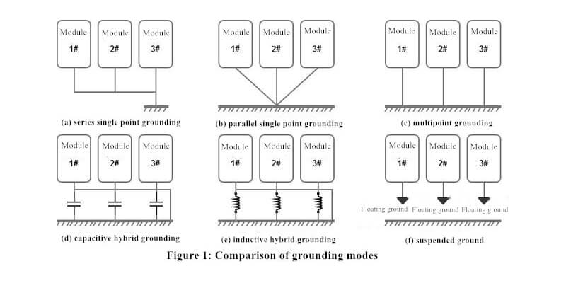
According to the physical structure, electronic equipment can be divided into three basic grounding methods: single point grounding, multi-point grounding and floating grounding. If classified according to performance, it can generally be divided into safety grounding, working grounding (digital grounding, analog grounding, power device grounding), anti surge grounding (lightning surge, power on surge) and anti-static grounding. In this section, we mainly introduce the grounding mode, as shown in Figure 1.
Single Point Grounding
Single point grounding is that in the whole system, only one physical point is defined as the grounding reference point, and all other points requiring grounding are connected to this point. Single point grounding is applicable to circuits with low frequency (below 1MHz). If the working frequency of the system is so high that the working wavelength is comparable to the length of the system grounding lead, the single point grounding mode will have a problem. As shown in Figure 1 (a) and (b).
When the length of the ground wire is close to 1 / 4 wavelength, it is like a transmission line with short circuit at the terminal. The current and voltage of the ground wire are distributed as standing waves. The ground wire becomes a radiation antenna and cannot play the role of “ground”. In order to reduce grounding impedance and avoid radiation, the length of ground wire shall be less than 1 / 20 wavelength. In the treatment of power circuit, single point grounding can be considered generally. For the digital circuits widely used by our company, because they contain rich high-order harmonics, it is generally not recommended to adopt single point grounding.
1) Series single point grounding
As shown in Figure 1 (a) is series single point grounding. For the series single point grounding mode, if the power of the modified circuit is large, it will produce a large circuit return, and a voltage drop will be generated on the limited impedance, resulting in the difference of voltage reference value between the circuit and the reference ground, which may make the system unable to work as expected.
If the system has a variety of circuits with different power levels, the series single point grounding mode cannot be adopted, because the high-power circuit produces a large return current, which will affect the low-power devices and circuits. If this grounding method must be adopted, the sensitive circuit must be directly set at the power input position, and the principle of low-power devices and circuits as far as possible. This method can be adopted if the grounding level of each circuit is not different.
2) Parallel single point grounding
As shown in Figure 1 (b) is parallel single point grounding. In the parallel single point grounding mode, each circuit unit is connected to the same place with ground wire alone. Its advantage is that the place of each circuit is only related to the ground current and low impedance of this circuit, and is not affected by other circuits. At low frequency, it can effectively avoid the low impedance interference between unit circuits, but there are also many disadvantages. It is mainly reflected in:
- Each circuit fern does not use independent ground wires for grounding. Multiple ground wires are required, which will inevitably increase the length of ground wires, thus increasing low impedance, complex structure and troublesome use;
- This grounding method will cause the coupling between the ground wires, and with the increase of frequency, the ground wire impedance, ground wire inductance and ground wire capacitance will increase. This grounding method is not suitable for high-frequency circuits.
Multi-point grounding
Multi-point grounding refers to that each grounding point in the equipment is directly connected to the nearest grounding plane to minimize the length of grounding lead and grounding impedance.
The structure of multi-point grounding circuit is simple, and the possible high-frequency standing wave phenomenon on the grounding wire is significantly reduced. It is suitable for occasions with high working frequency (> 10MHz).
When the working frequency of the electronic system is higher than 1MHz, so that the working wavelength can be compared with the length of the system grounding lead. The ground wire is like a transmission line with short-circuit terminal. The current and voltage of the ground wire are distributed as standing waves, and the ground wire becomes a radiation antenna, which can not cause the function of the ground wire. In order to reduce grounding impedance and avoid radiation, the length of ground wire should be less than 1 / 20 wavelength, so the single point grounding method is unreasonable. multi-point grounding technology is usually used. The structure of multi-point grounding circuit is simple, and the phenomenon of high-frequency standing wave on the grounding wire is significantly reduced. However, multi-point grounding may lead to the formation of many grounding loops inside the equipment, thus reducing the resistance of the equipment to external electromagnetic fields. In the case of multi-point grounding, pay attention to the ground loop, especially when networking between different modules and equipment.
Generally speaking, when the frequency is below 1MHz, the single point grounding mode can be adopted. When the frequency is higher than 10MHz, the multi-point grounding mode can be adopted. When the frequency is 1-10mhz, as long as the longest transmission line length is less than 1/20 wavelength, the single point grounding mode can be used to avoid impedance coupling. High frequency and low frequency hybrid circuit can adopt hybrid grounding mode.
Multi-point grounding case (taking switch products as an example)
The system working frequency of the switch products is above 10MHz, and most of them are digital circuits containing rich high-order harmonics. It is recommended that all the grounds except BGND be connected together on the backplane (multi-point connection: that is, all the grounds except BGND, such as GND, PGND, AGND, DGND, etc., are directly connected to the backplane from the single board).
Hybrid grounding
Hybrid grounding is a combination of single point grounding and multi-point grounding. This grounding method is often used when there are high and low frequency mixed frequencies in PCB.
(d) and (E) in Figure 1, as above, provide two hybrid grounding methods. For “(d) capacitive hybrid grounding”, that is, capacitive coupling circuit, it presents a single point grounding structure at low frequency and a multi-point grounding state at high frequency, because the capacitor divides the high-frequency current to the ground. The selection of capacitance must be based on the frequency used and the expected flow direction of grounding current. The use of capacitors and inductors in grounding topology enables us to control RF current in an optimized design. By determining the path through which the RF current passes, the wiring of PCB can be controlled. Lack of awareness of RF current circuits can lead to radiation or sensitivity problems. If you want to understand the principle of capacitance or inductance in detail, you can check the content about inductance and capacitance filtering characteristics in the filter circuit in EMC design of PCB I wrote last time.
Floating ground
Floating ground refers to the electrical isolation between the grounding system of equipment and the grounding of shell components. To prevent the electromagnetic interference of the shell from being transmitted to the equipment. However, since the equipment is not connected to the public ground, the suspended ground is easy to generate electrostatic accumulation between them. When the charge accumulates to a certain extent, an electric field will be formed between the equipment and the public ground, and the generated potential difference may cause severe electrostatic discharge and interference. Suspended ground is generally not suitable for communication systems.
Floating ground can make the isolation resistance between power ground (strong current ground) and signal ground (weak current ground) very large, so it can prevent electromagnetic interference caused by common ground impedance circuit coupling. Its disadvantage is that the circuit is easily affected by parasitic capacitance, which changes the ground potential of the circuit and increases the inductive interference to the analog circuit.
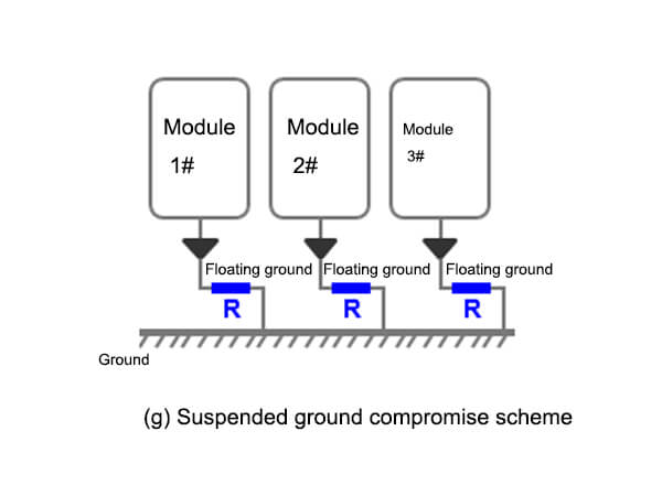
A compromise scheme is to bridge a discharge resistance with large resistance between the floating ground and the common ground (as shown in “(g) floating ground compromise scheme) to release the accumulated charge. Pay attention to control the impedance of release resistance. Too low resistance will affect the qualification of equipment leakage current.
Several precautions for floating technology
- Improve the insulation resistance of the floating ground system to the ground as much as possible, so as to effectively reduce the common mode interference current entering the floating ground system.
- Note the parasitic capacitance of the floating system to the ground, and the high-frequency interference signal may still be coupled to the floating system through the parasitic capacitance.
- Floating ground technology must be combined with electromagnetic compatibility technologies such as shielding and isolation in order to obtain better expected results.
- When using floating ground technology, attention should be paid to the harm of static electricity and voltage counterattack to equipment and personnel.


