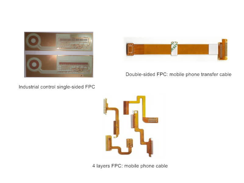
With the development of electronic products, the technical demand of using FPC soft board to connect to PCB is higher and higher. But how to connect them? Following we will introduce several common connection and welding methods between FPC and PCB in the industry.
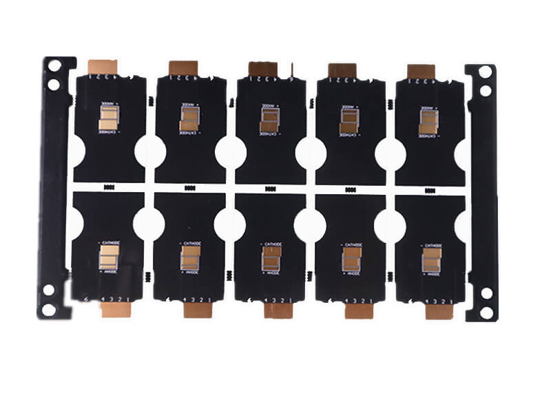
FPC ( “flexible printed circuit board” or “flexible circuit board”) is currently used in a variety of electronic products, especially wearable devices and lightweight handheld devices. Although PCBA process has developed the ability to directly weld electronic parts on FPC, its solder ability and quality reliability are still poor, such as which “I / O connectors” for end users, such as micro USB The connectors for USBC charging and data transmission, large BGA and QFN are also not recommended to be welded to FPC.
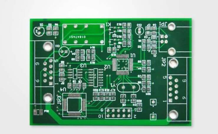
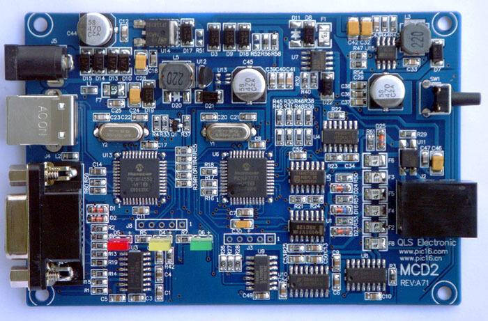
Generally, FPC needs to be connected to rigid PCB eventually, and the process of FPC connecting to PCB is used:


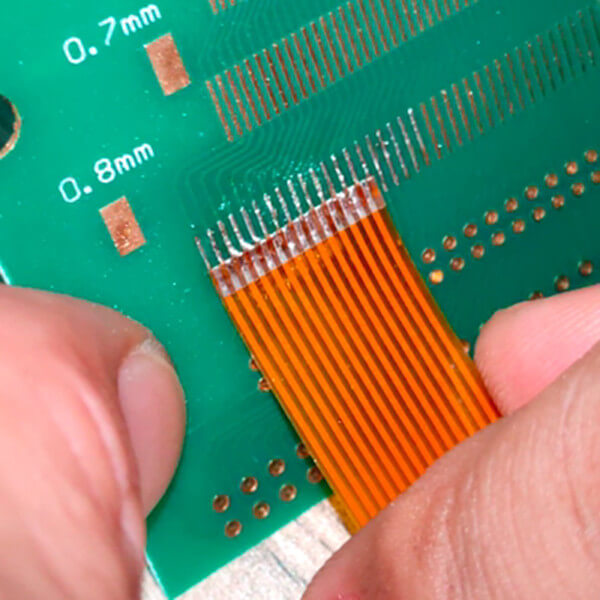
Soldering Process Between FPC and PCB
1. Manual Soldering
Manual soldering of flexible board to circuit board is the cheapest process of all flexible board welding processes. Some can operate without using fixtures at all, but its welding quality is also the least reliable process, because manual welding is easy to cause quality problems such as empty welding, false welding, false welding and bridge short path. This is because during manual welding, the soft board is easy to move or tilt up when the soldering iron head is removed and the solder is not cured. After the solder is cured, false welding, empty welding and other results are formed.
Therefore, in manual soldering, it is best to use heavy objects to press on the soft plate until it is removed after welding, which can greatly improve the welding yield. In addition, the gold finger of soft plate welding should be provided with through hole (PTH), which can increase vision to confirm whether the welding is good, and also reduce the risk of tin overflow and short circuit.
Generally speaking, if the design has not been decided (lock down), in order to reduce the cost of fixture design and production, a small amount of manual electric soldering iron can be used to weld the soft board to verify the function of Rd. Manual welding is strongly recommended for mass production.
2. HotBar Soldering
The principle of HotBar soldering is basically to use the [Joule heat] generated when the so-called [pulse current] flows through metal materials with high resistance characteristics such as molybdenum and titanium to heat the [thermal modes / heater tip], and then heat and melt the solder paste printed on PCB and connect it with FPC through the thermal head to achieve the purpose of welding.
Therefore, during HotBar operation, there must be HotBar machine and carrier to fix FPC on PCB. As long as FPC and PCB are well designed, they can basically achieve the goal of mass production and certain yield.
▪ The welding quality of HotBar basically depends on the design.
▪ Then there is the spacing of FPC gold fingers. The larger the spacing, the easier it is to produce and the higher the yield. However, the design requirements are smaller and smaller, which also makes HotBar more and more difficult to do and straightforward.
▪ Finally, there is the problem of process control. For example, the control of solder paste quantity, whether the application of flux is in place during HotBar, the setting of temperature, pressure and time of HotBar, and the capacity of HotBar machine (whether the pressure of hot indenter can be programmed).
In addition, the design of some HotBar soft boards cannot achieve the effect of effective heat conduction. At this time, it may be necessary to consider whether to use SnBi low-temperature solder paste, but the low-temperature solder paste is brittle, so it is recommended to strengthen the auxiliary structure.
3. Reflow Soldering
The reflow soldering process is basically to print solder paste on the PCB, then place the FPC in front of the reflow furnace, and use the reflow carrier of the upper cover and lower seat to pass through the reflow furnace. The upper and lower tools use magnetic buttons to ensure that the FPC position will not move, and the FPC solder joints will not tilt up during reflow.
There are several precautions for this FPC reflow process:


Reflow soldering is suitable for products without too many parts on PCB and parts on FPC. Otherwise, the defect rate caused by touching other parts or solder paste should be very high, and fine pitch FPC should not be suitable.
4. Laser Soldering
Laser soldering is to convert laser energy into heat energy to achieve the purpose of welding, so its welding is usually used to directly heat the laser at the position of solder.
This kind of laser soldering equipment is usually a special-purpose machine rather than a general-purpose machine. Its energy is generally not suitable for performing other operations, so the equipment cost is not cheap. Unless it is a product with large output, it is not recommended to calculate the ROI by yourself!
5. ACF (Anisotropic Conductive Film)
When soldering tin cannot be used to weld FPC and PCB, ACF (anisotropic conductive film) may be considered to conduct the electronic signals of FPC and PCB. The processing temperature of ACF is lower than that of hotbar, so there is no need to worry about the burning problem of FPC. The operation mode of ACF is actually similar to that of hotbar, but ACF is simpler. It is actually a bit like adhesive, which is placed between the golden fingers of PCB and FPC, Then the connection can be completed by heating and pressurization. Some equipment and machines can even set different temperatures and pressures, which can be used for hotbar and ACF processes at the same time.
However, the biggest disadvantage of ACF is that its adhesive is easy to fail and peel off after using for a period of time, so additional mechanisms must be added to ensure that FPC will not loose from PCB.

