Purpose
In order to unify and standardize the manufacturing standard, instruction preparation and production control of back drill plate.
Scope of Application
All plates with back drilling process.
Terms and Definitions
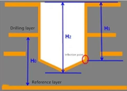
Back drilling: Use the depth control function of the mechanical drill to drill npth holes with certain depth requirements with a larger diameter drill knife and plated with hole copper. The schematic diagram of back drilled hole type is as follows.
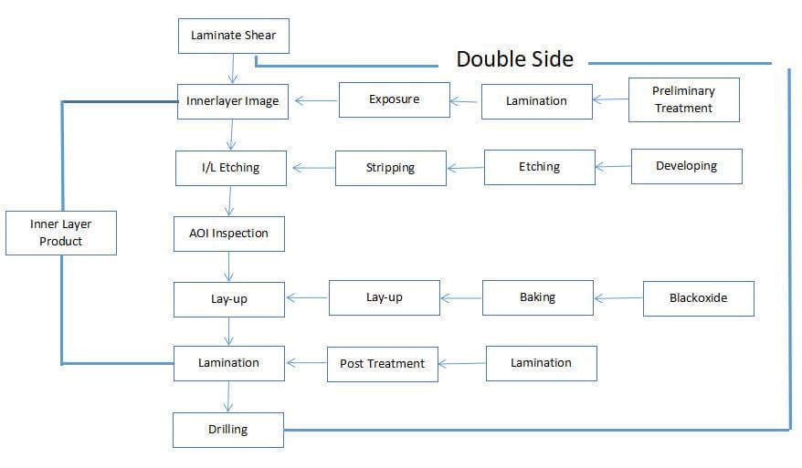
Operation Flow
Operation Basic Configuration
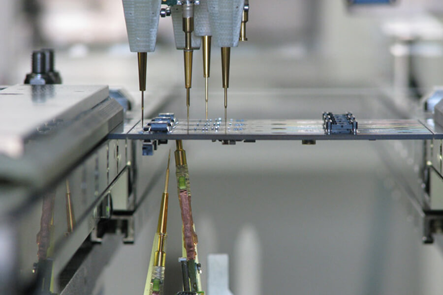
Operating Machine: Family drilling rig with CCD radio deep control function.
Materials Used: Base plate, paperboard, phenolic cover plate, 0.125mm aluminum sheet, wrinkled adhesive tape.
Auxiliary Tools: Drill nozzle, pin, pliers, hammer.
Operation Content
1. Definition of depth control capability: clip pin manufacturing capability
Back Drilling Depth (mm) | ≦0.66 | 1.2 | 1.8 | 2.5 |
Depth Control Tolerance (MIL) | ±2.4 | ±2.7 | ±3.8 | ±4.7 |
Required Minimum Dielectric Layer Thickness (MIL) | 6.8 | 7.5 | 9.7 | 11.4 |
During the review of engineering design data, it is necessary to ensure the thickness of medium layer H × 90% meet the above minimum requirements. When the requirements of electric board capacity (preferred) are met, the drilling rig requirements are not made in the instructions; When the electric board capacity is exceeded, the pin clamping capacity shall be selected, and the pin clamping production shall be indicated in the instruction. Clamping pin production capacity: plate length ≤ 29.5 “and plate thickness ≤ 3.5mm. When the above two capabilities are exceeded, the engineering department asks the customer to relax the tolerance or submit it for business review.
2. Programming of back drill belt
- Insert “M18 zxx” after each knife in the program to set the tripping depth of this drill nozzle, and add “M19” at the end of this knife to turn off the function of “M18”.
- When the length dimension of the panel is ≥ 29.5 “, if it is greater than this dimension, the following rules shall be followed when dividing the drilling program: | ymax – Ymin |
29.5 “(ymax and Ymin are the maximum and minimum values of X and Y coordinates in the program respectively), that is, ensure the maximum coordinate difference between X and Y in the program.
It shall be smaller than the maximum machining size of the machine. - For example, the back drilling program of h18104ti178a1 is as follows (the instructions added in italics):
M48
T01C0.800
T02C0.900
T03C0.800
….
….
….
%
T01
M18z00125 setting The tripping depth of T01 is 1.25mm (the data in the program are leading zeros)
M25
X15177Y-008186
X153405
….
….
….
M19 turns off M18 function
T02
M18z00125 sets the tripping depth of T02 to 1.25mm (the data in the program are leading zeros)
M25
X15177Y-009671
3. Operation process of setting back drilling depth value
- After drilling, the production department / DR will send the back drilling plate to the material testing room for slicing. The sliced plate will not be scrapped. It will be normally produced to the “back drilling process” for back drilling head plate test.
- Each depth is taken by the physical testing room, 2pcs are taken from the plate edge and the plate middle section respectively, and the section data H (not copper plated here) and H value are read and recorded in the drilling section test report for process analysis. The setting standard of back drilling depth is: the median value of average thickness of aluminum sheet + the median value of standard running depth.
- Fabrication of back drill positioning holes: the back drill model needs to be produced by clamping pin. A pair of back drill positioning holes (for back drill positioning on CS surface) shall be added in the 10mm area on the left of the normal target hole. If it is back drill on both sides, another pair of back drill positioning holes shall be added in the 10mm area on the right (for back drill positioning on SS surface). The positioning hole shall be placed in the middle as far as possible, and the distance between the positioning hole and the plate edge shall be ≤ 10 “. Add the pin coordinates of the clamp in the engineering instructions. All positioning holes required for back drilling shall be sealed.
4. Fabrication of back drilling test hole
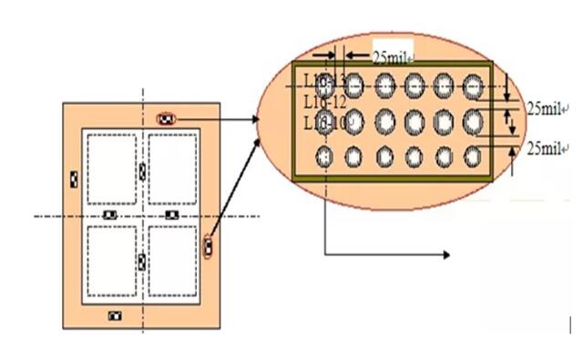
- One group of back holes shall be added for each kind of back holes around the production plate edge, and 6 back holes / group shall be drilled for trial, and the hole edge shall be added Ls-m negative sign (indicating drilling from layer s to layer m) Layer). For each plate with 2 or more units, back drilling test holes shall be added between the units in the plate. It is required that the distance between the trial drilling hole and the outer edge of the unit shall be ≥ 5mm. In addition, for holes with a variety of back drilling depths and different aperture requirements, it is required to arrange all back drilling holes symmetrically in turn for slice analysis. Based on the maximum back hole diameter, the distance from the back hole wall to the hole wall is designed as 25mil. The schematic diagram is as follows:
- The test drilling LM and the inner layer pad are made by 10mil larger than the single side of the back drilling tool diameter, and the remaining layers ln are designed to be larger than the single side of the back drilling tool diameter The outer layer of 10mil base material ring shall be made of large copper sheet. During the first drilling, the test drilling at the plate edge shall be incorporated into the drilling belt.
- For back drilling, the two trial drilling modules at the upper and lower plate edges are programmed as the out and feed holes of back drilling.
- The first drill of the first plate can be made in batch only after it is determined to be qualified through slice measurement and analysis.
5. Key production process control
- Blanking: after blanking, 100% of the plate thickness shall be measured, and four plate edges of each plate shall be measured and recorded. If the plate thickness exceeds the standard, it is not allowed to pass through the plate.
- Press fit
(1) Production board size is less than 24“ × 28 “is produced by mass Lam press;
(2) Engineering design for Semi cured sheet pressing plate of the same batch;
(3) After lamination, IPQC is responsible for measuring the plate thickness, with sampling frequency of 30pnl and sampling frequency of 6pnl. - Drilling:
(1) For external production, drilling equipment with CCD radio deep control measurement function is used.
(2) The back drilling adopts a new tungsten steel integrated knife, 1 piece / stack, corresponding to the normal drilling parameters, but the cutting speed is controlled at 0.5-1m/min. Control hole position accuracy + / – 2mil.
(3) When only one side has back drilling, the first drill hole and back drill hole shall be drilled from the same surface; When there are back holes on both sides, it is necessary to drill on both sides according to the engineering design requirements.
(4) Fabrication of M hole (anti reverse blind hole): CS surface is below the slicing hole, and SS surface is at the lower left corner of the plate; Use a 1.5mm hole knife; Single out to form a The knife is marked with 1.55 in the program; Han family drilling rig control drilling tool offset (offset) Z + 0.8. - Copper plating:
(1) One time copper plating shall be used for back drilling as far as possible to avoid hole breaking caused by tin on secondary copper
(2) In order to ensure the effect of copper plating and the uniformity of copper plating, the tank can be transformed into VCP spraying mode for stirring, and the proportion of lustrous agent can be adjusted at the same time.
(3) After pre-treatment and post-treatment, the back drill plate must be drilled downward, and the drying speed shall be controlled at 100-110 ℃, and the speed shall be controlled at 1-1.5m/min, so as to reduce the oxidation problem at the back drill edge. This method is suitable for the production of the horizontal line of the back drill plate in the plant.

